Well this was a fun project and I'm very pleased with the results. Again, I have to thank the wonderful folks (you know who you are) on the best Goldwing Message Board on the internet. Without their expertise and generosity, I would not have been able to tackle this project. Thanx guys!
I approached this a little differently than most of the installs I saw on the internet for 3 reasons. One, I didn't want to pull that whole harness out from under the seat through the back fender and unwrap it. I really couldn't because there was so much wiring and other components for my trailer hitch. Two, I wanted the Wig Wag module under the seat for easier access in case I need to get to it again in the future. And three, I wanted to install a bypass switch on the modulator because I discovered that brake modulators are illegal in NJ and you will fail inspection with one. So now I can bypass it for inspection instead of pulling the bike apart and re-wiring things. Also, if an LEO busts my balls, I can appease him. Same with my headlight mods. This way, when I'm tooling around the country and go into a State where they're illegal, I can remedy it easily.
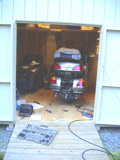
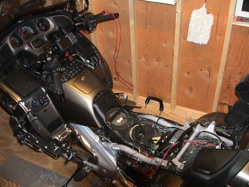
OK, here we go! Here's my humble stable for my wing and trailer and everything else associated with this bike.
It's a little tight, but it works.
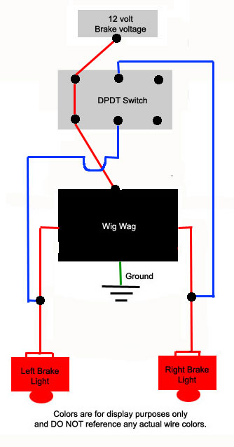
Here's a crude schematic of my plan.
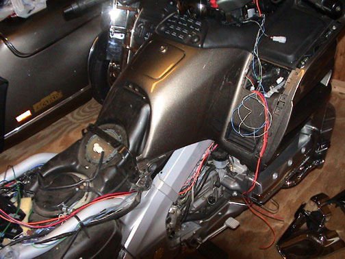
I removed the back fender, lower trunk cover and trim, seat, motor covers, right side baker air wings with associated trim, and the right side control panel. That's the easy part.
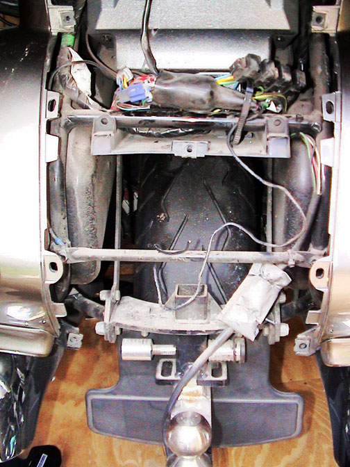
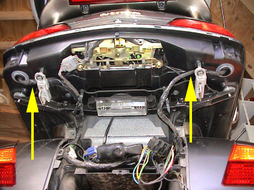
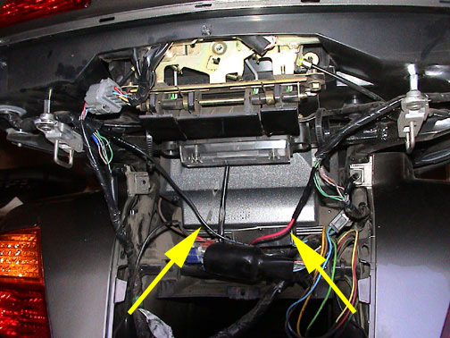
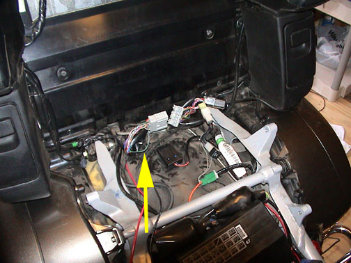
Here's the back of the bike with fender/lower trunk cover removed. You can see above the tire all the crap that would have to be moved/removed to go through to the cockpit. I didn't want to deal with that.
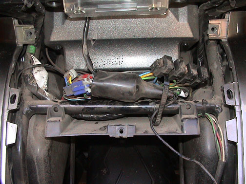
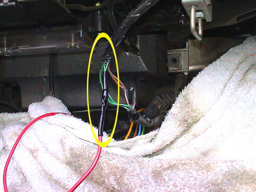
I only wanted to modulate the trunk lights. So instead of trying to fish out the pertinent wires from that big harness, I went right to the source and tapped into the wires right where they go up into the trunk.
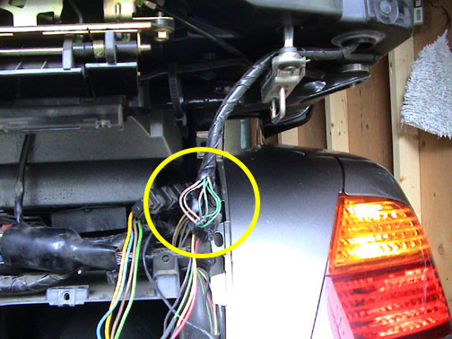
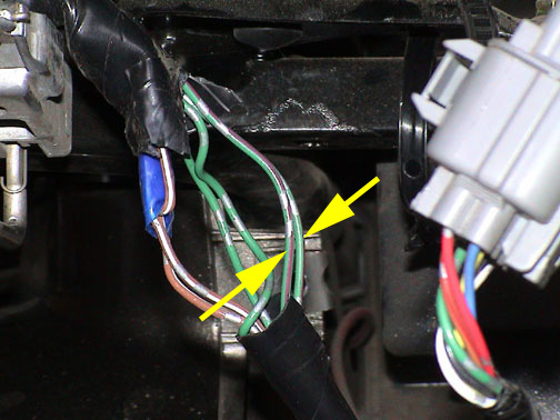
I carefully cut through the tape to expose the wires. The wires of focus are the green wire with red stripe which are feeding the 12v to the bulbs. There are two of them. Cut them both, leaving yourself enough room to work.
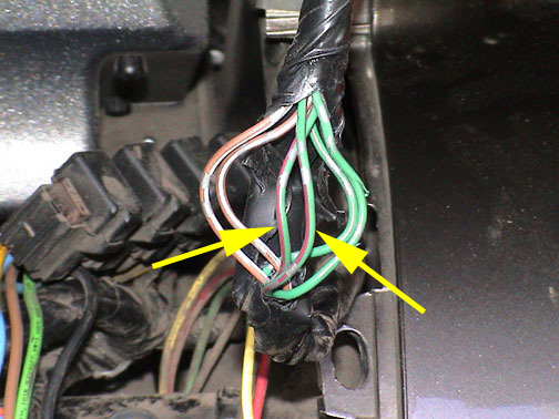
Take the two ends that run up to the lights and twist them together, then splice that to a wire that you will run under the trunk to the cockpit. Tape the other two wires off. I used 16 gage marine grade wire. Red for the right side, black for the left. Use about a 4 foot pieces here to give yourself some play, and I ran them from the cockpit, under the trunk and over the fender. I soldered all wire splices, and they were double heat shrink wrapped.
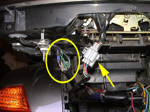
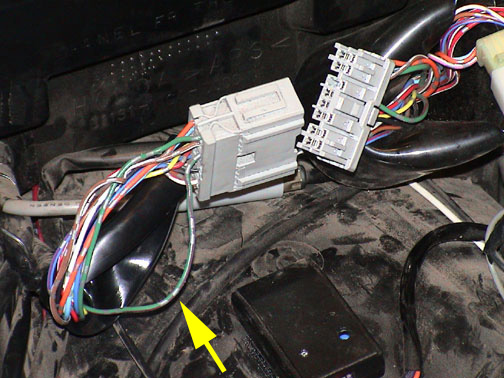
Do the same on the left side with your black wire. It helps to take that grey plug (yellow arrow) off the clip to make more room.
The brake lights are wired. Here's the back end wrapped back up with my two brake wires running forward with the ends sitting in the cockpit by the relay bank.
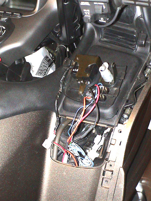
Pull the gray connector out of it's boot under the seat and separate the two halves.
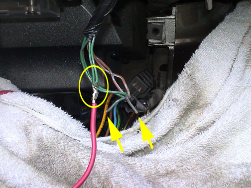
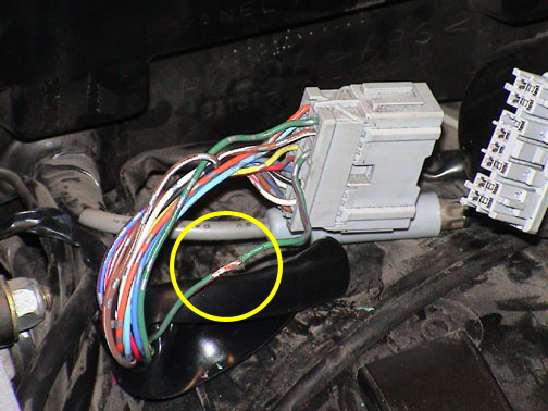
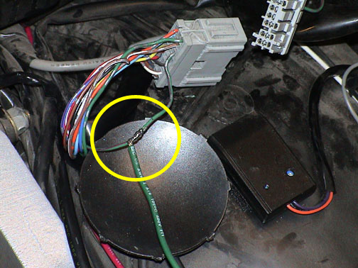
This is where I took my 12v brake signal for the input to the Wig Wag.
Again it's the green wire with the red stripe. I used a test light to confirm it was the brake signal, and I tapped into the male side of the plug as it had more room to work.
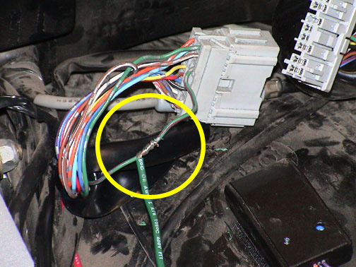
I carefully exposed the wire with a razor blade.
I spliced in my input power wire here and soldered it. I used a 4 foot piece of green. The little "dish" you see under the soldered connection is the punchout from the lower cowl for the fog lights. It comes in real handy when soldering on the bike to keep solder drippings from falling where you don't want them.
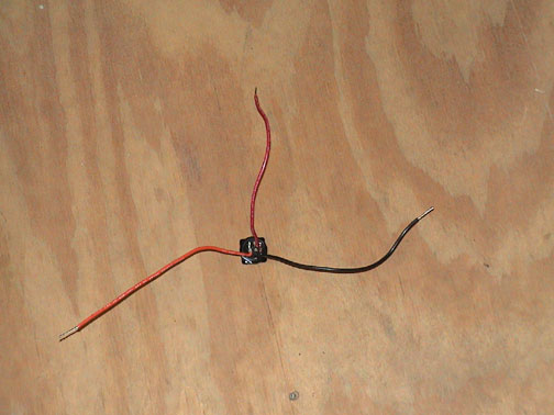
OK, here's the switch that I used. A double pole double throw rocker switch from Radio Shack for about 3 bucks. (you'll see a better picture of it below) I pre-wired it with 10 inch strands to make it easier to install. The wiring of the switch is shown in the schematic at the top of this page.
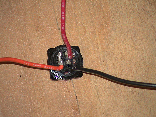
Here's the switch wiring close up. I put heat shrink tubing on the terminals and wires at the switch for insulation and reinforcement.

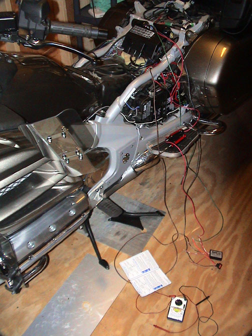
Before installing the switch and soldering and shrink tubing everything, I first hooked everything up to test my application and check myself. I would have hated to have just put this all together and it didn't work.

Looks pretty scary, huh? Notice in the second picture down, the wire wrapped around the front brake handle. That was so I could stand behind the bike and pull on the wire to activate the brakes and see if everything was working. Cool... it was.
OK, so I installed the switch into the right control panel under the heated grips control. Sorry, I didn't photograph that... it was getting late and I wanted to get done. I spliced matching lengths of wire to the switch and fished them under the top shelter and along the frame, to meet the wires from the brake lights and the Wig Wag unit at the relay bank. The thin blue, white and grey wires are from my headlight modulator controls.
Here's the back of the control panel cleaned up with all wires pulled into place.
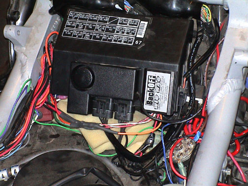
I connected my splices from the front and the back at the Wig Wag unit and hooked everything up. I attached the Wig Wag to the top of the relay bank with velcro, right next to my Scorpio Alarm, also attached with velcro.
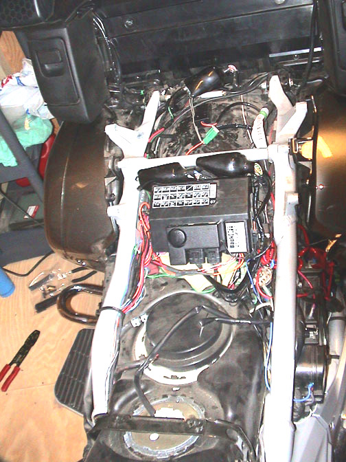
Here's a closer shot with everything cleaned up. The Wig Wag ground runs to the EC Ground Block visible on the right.
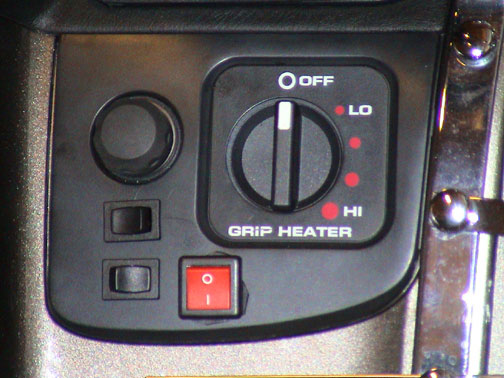
Here's how the control panel looks with the switch installed. The little pieces of rubber you see sticking out from under the switch are from a rubber gasket I put under the switch. When I tightened up the switch it squeezed some rubber out. I cleaned it up with an exacto knife and now it looks great.
And that's it! Works like a charm. Here's my current cockpit.
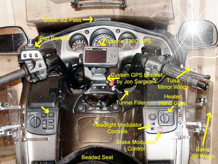
Thanks for viewing... see ya on the road!
[Back To FloydWeb Page] [Back To My Music Page] [Back To Welcome Page] [Back to Goldwing Page]